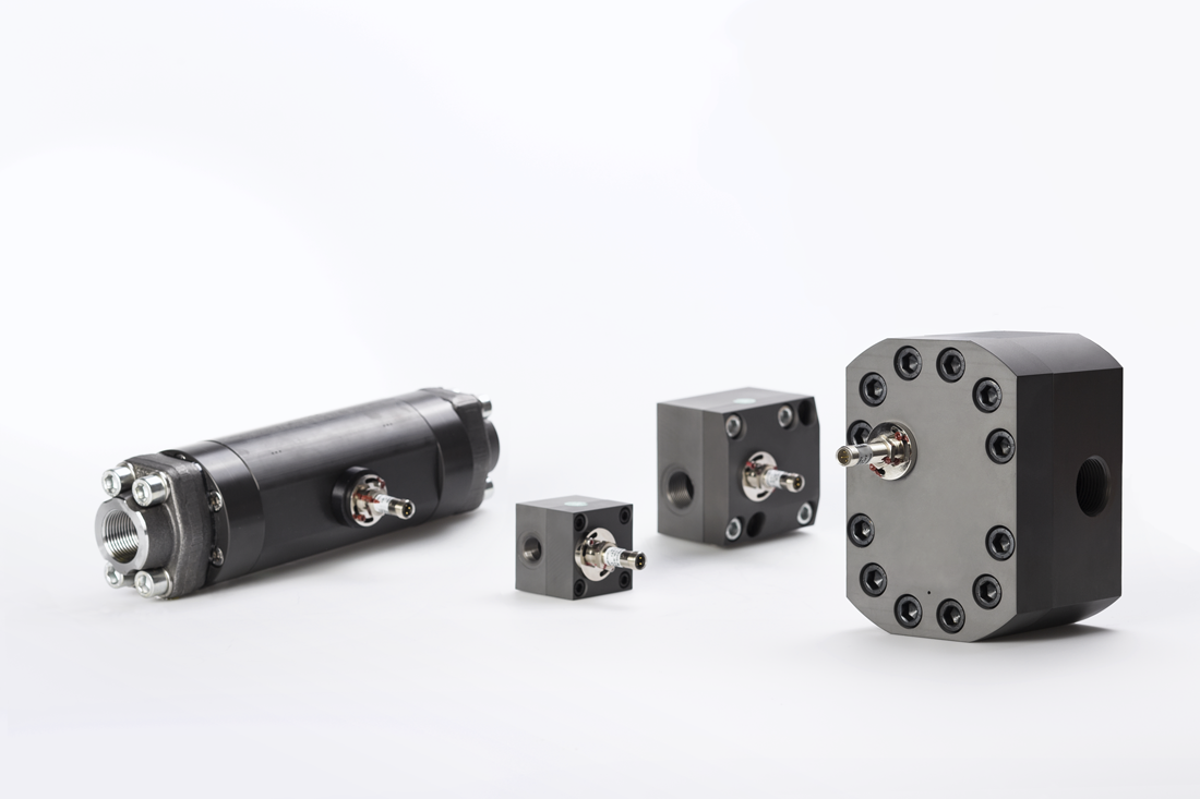
Koolance s inline flow meters provide electronic indication of real time coolant flow rate.
Engine coolant flow measurement.
We supply products worldwide to heavy industry defence motorsport and off highway amongst many other markets that demand robust accurate control and measurement in extreme operating conditions.
Check if the coolant is circulating.
Coolant flow and head gasket design.
The flow through each orifice in the head gasket can be determined by measuring the pressure drop across each orifice while coolant is being forced through the engine.
Measurement devices for monitoring coolant flow volume lpm gpm.
A flow monitor is removably connectable in serial fluid communication with a coolant conduit of an engine cooling system.
Low profile inline flow meters with steel or polymer bodies led lighting and straight or 180 degree flow paths.
The measured magnitude of this differential pressure allows a microprocessor or similarly configured component to determine.
Approximate read range is 2 0 15 lpm 32 240 gph.
Experimental errors in coolant flow rate and temperature cause variations in the measurement of engine coolant heat rejection.
Gill sensors controls design and manufacture level position condition and flow sensors for demanding and critical environments as well as engine controls.
The thermostat provides control for your engine s warm up period.
This model also integrates a thermistor coolant temperature sensor.
Park your vehicle and allow the engine to cool.
When the engine is warm visually watch the coolant in the cooling system to see if it is circulating.
Flowsonic hf is designed to measure high volume flows of coolant and lubricant in all vehicle types.
Therefore based on the design of the cooling system and flow through the engine it is very important to double check that the cylinder head is matched to the block and that the head gasket is installed correctly end for end so that all of the cooling.
A flow meter frequency adapter can be used to convert flow meter values to signals similar to fan rpm tachometry.
G 1 4 bspp fitting threads and primary materials are a stainless steel body with brass threads.
Unscrew and remove the pressure cap from the cooling system and keep it aside.
The heat rejection errors can range from 3 to 20 kw and become unacceptably large for precise design.
Remove the cooling system pressure cap.
By providing a flow restrictor between upstream and downstream ports a differential pressure is created between the upstream and downstream ports.
Coolant flow has a direct relationship to area and an exponential relationship to pressure.
In order to measure the engine cylinder coolant heat rejection directly experimental errors need to be minimized.

